For those who are interested in understanding the intricacies of payphone wiring, this article provides a comprehensive guide to the Western Electric payphone wiring diagram. The diagram is a crucial tool for anyone looking to repair or install payphones, as it outlines the connections between various components such as the coin return, coin acceptor, and the phone itself. With the rise of digital communication, payphones have become less common, but they still play a vital role in many communities, especially in areas where cell phone coverage is limited.
Western Electric, a renowned company in the telecommunications industry, has developed a detailed wiring diagram that is easy to follow and understand. This diagram is particularly useful for those who are new to payphone maintenance or repair, as it provides a clear visual representation of the connections and components involved. By studying this diagram, individuals can gain a deeper understanding of how payphones function and how to troubleshoot common issues that may arise. Whether you're a professional technician or a DIY enthusiast, this wiring diagram is an essential resource for anyone working with payphones.
what are the key components of a Western Electric payphone wiring diagram
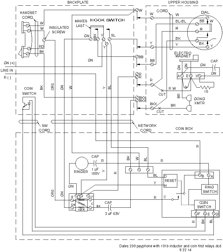 The key components of a Western Electric payphone wiring diagram include:
Coin Return: This component is responsible for returning coins inserted by the user into the payphone. It is connected to the wiring diagram to ensure proper functioning of the coin return mechanism.
Coin Acceptor: This component is responsible for accepting coins inserted by the user into the payphone. It is connected to the wiring diagram to ensure proper functioning of the coin acceptor mechanism.
Phone: The phone itself is a crucial component in the wiring diagram, as it is connected to the coin acceptor and coin return mechanisms. It is also connected to the telephone line wires, which allow users to make calls.
Telephone Line Wires: These wires are attached to the payphone and are used to connect the payphone to the telephone line. The "tip" and "ring" terminal screws are the two that you wire your phone line to, ensuring proper connection to the telephone network.
Ringer: The ringer is a component that is connected to the wiring diagram to ensure proper functioning of the payphone's ringing mechanism. It is typically connected to the 48 Vdc line and is used to signal incoming calls.
Detector Circuit: This component is responsible for detecting when a call is being made and is connected to the wiring diagram to ensure proper functioning of the payphone's call detection mechanism.
Zener Diode: This component is used to block current to the FET (Field-Effect Transistor) in the payphone's circuitry. It is connected to the wiring diagram to ensure proper functioning of the payphone's electronic components.
These components are crucial in understanding the Western Electric payphone wiring diagram and are essential for the proper functioning of the payphone.
The key components of a Western Electric payphone wiring diagram include:
Coin Return: This component is responsible for returning coins inserted by the user into the payphone. It is connected to the wiring diagram to ensure proper functioning of the coin return mechanism.
Coin Acceptor: This component is responsible for accepting coins inserted by the user into the payphone. It is connected to the wiring diagram to ensure proper functioning of the coin acceptor mechanism.
Phone: The phone itself is a crucial component in the wiring diagram, as it is connected to the coin acceptor and coin return mechanisms. It is also connected to the telephone line wires, which allow users to make calls.
Telephone Line Wires: These wires are attached to the payphone and are used to connect the payphone to the telephone line. The "tip" and "ring" terminal screws are the two that you wire your phone line to, ensuring proper connection to the telephone network.
Ringer: The ringer is a component that is connected to the wiring diagram to ensure proper functioning of the payphone's ringing mechanism. It is typically connected to the 48 Vdc line and is used to signal incoming calls.
Detector Circuit: This component is responsible for detecting when a call is being made and is connected to the wiring diagram to ensure proper functioning of the payphone's call detection mechanism.
Zener Diode: This component is used to block current to the FET (Field-Effect Transistor) in the payphone's circuitry. It is connected to the wiring diagram to ensure proper functioning of the payphone's electronic components.
These components are crucial in understanding the Western Electric payphone wiring diagram and are essential for the proper functioning of the payphone.what are the specific functions of terminals B, R, C, RR, and GN in a Western Electric payphone
 The specific functions of terminals B, R, C, RR, and GN in a Western Electric payphone are as follows:
B: This terminal is connected to the "tip" of the telephone line wire. It is used to transmit the audio signal from the payphone to the telephone network.
R: This terminal is connected to the "ring" of the telephone line wire. It is used to transmit the ringing signal from the telephone network to the payphone.
C: This terminal is connected to the coin return mechanism in the payphone. It is used to return coins inserted by the user into the payphone.
RR: This terminal is connected to the coin acceptor mechanism in the payphone. It is used to accept coins inserted by the user into the payphone.
GN: This terminal is connected to the ground wire of the telephone line. It is used to provide a grounding path for the payphone's electrical components and to ensure proper functioning of the phone.
These terminals are crucial in understanding the wiring diagram of a Western Electric payphone and are essential for the proper functioning of the payphone's various components.
The specific functions of terminals B, R, C, RR, and GN in a Western Electric payphone are as follows:
B: This terminal is connected to the "tip" of the telephone line wire. It is used to transmit the audio signal from the payphone to the telephone network.
R: This terminal is connected to the "ring" of the telephone line wire. It is used to transmit the ringing signal from the telephone network to the payphone.
C: This terminal is connected to the coin return mechanism in the payphone. It is used to return coins inserted by the user into the payphone.
RR: This terminal is connected to the coin acceptor mechanism in the payphone. It is used to accept coins inserted by the user into the payphone.
GN: This terminal is connected to the ground wire of the telephone line. It is used to provide a grounding path for the payphone's electrical components and to ensure proper functioning of the phone.
These terminals are crucial in understanding the wiring diagram of a Western Electric payphone and are essential for the proper functioning of the payphone's various components.how do the lengths of the wires for terminals B, R, C, RR, and GN affect the payphone's performance
The lengths of the wires for terminals B, R, C, RR, and GN in a Western Electric payphone do not directly affect the payphone's performance. These lengths are primarily determined by the physical layout and design of the payphone's internal components and wiring, which are standardized across different models of payphones. The lengths of these wires are typically specified in the payphone's wiring diagram and are intended to ensure proper connections and functioning of the payphone's various components. For example, the lengths of the wires for terminals B, R, C, RR, and GN in the Western Electric 200 series payphones are specified as follows: B: 23 inches R: 23 inches C: 23 inches RR: 16 inches GN: 14 inches These lengths are designed to accommodate the physical layout of the payphone's internal components and wiring, ensuring that the payphone functions correctly and efficiently. Any changes to these lengths could potentially affect the payphone's performance, but these changes would typically be made during the manufacturing process and would not be something that a user would need to consider. In summary, the lengths of the wires for terminals B, R, C, RR, and GN in a Western Electric payphone are primarily determined by the payphone's design and are not a factor in its performance. #EANF#As you have now concluded your exploration of the Western Electric payphone wiring diagram, we hope that you have gained valuable insights into the intricacies of this complex system. The diagram, as outlined in the article, provides a comprehensive guide to understanding the connections between various components such as the coin return, coin acceptor, and the phone itself. This knowledge is crucial for anyone looking to repair or install payphones, especially in areas where cell phone coverage is limited. By studying this diagram, individuals can gain a deeper understanding of how payphones function and how to troubleshoot common issues that may arise.
We appreciate your interest in this topic and hope that you have found the information presented here informative and helpful. If you have any further questions or concerns regarding the Western Electric payphone wiring diagram or any other related topics, please feel free to reach out to us. Remember that understanding the intricacies of payphone wiring is essential for ensuring the proper functioning of these devices, which continue to play a vital role in many communities. By staying informed about these systems, you can contribute to their continued effectiveness and reliability. Thank you for visiting our blog and we wish you all the best in your future endeavors.


No comments:
Post a Comment